
8 - Inspection and test techniques
8.1 - Optical microscopy, automatic optical inspection
Optical microscopes
For components, substrates and assemblies, the most important testing method is optical inspection. Its instrument is the optical microscope, which is a magnifier device consisting of several complex lens-systems. The condenser projects light onto the specimen. The objective produces a magnified real image (this is at the intermediate image plane), which is magnified more with the eyepiece. The image produced by the eyepiece is the magnified virtual image (see on the bottom). It also produces a smaller real image (film plane), which can be used for make a photo. The total magnification is the product of the magnification values. Resolution is a characteristic of the microscope: it is the minimal distance between two distinguishable points.
Resolution is a characteristic of the microscope: the minimal distance between two distinguishable points:where is the resolution, is the wavelength of illuminating light, and is the Numerical Aperture. The resolution is better, where NA is higher. The Numerical aperture is the characteristic of the lens:where is the refraction index of the lens, and is the half viewing angle, which depends on the material and the geometry of the lens.
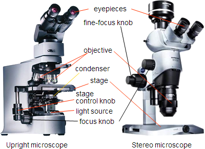
The two main types of optical microscopes are stereomicroscopes and upright microscopes. Stereomicroscopes usually have external illumination, for example, a ring-shaped or a fibre optical lamp. Side illumination also can be carried out with them, when the elementary light sources (lLEDs) are switched on in groups, or with moving the fibre optic end to the side. Usually larger samples can be examined with it with good depth of field (DOF) and relatively low magnifications (about 10–100 times). Depth of field is the sharpness of points which are at different distances. The depth of field is good if we see different height points of an image with the same sharpness.
Upright microscopes use built-in illumination. To increase the magnification, the objective gets very close, only to a few millimeters, or closer to the sample. It is used to inspect samples, for example cross-sections at high magnification values (between 50 and 1000 times). Upright microscopes contain multiple objective lens-systems, one for each magnification values. The selection of the tubes is carried out by a rotatable disc. Both types have a camera-ocular lens, to which a digital camera can be attached.
Upright microscopes use built-in illumination. To increase the magnification, the objective gets very close, only to a few millimeters, or closer to the sample. It is used to inspect samples, for example cross-sections at high magnification values (between 50 and 1000 times). Upright microscopes contain multiple objective lens-systems, one for each magnification values. The selection of the tubes is carried out by a rotatable disc. Both types have a camera-ocular lens, to which a digital camera can be attached.
Imaging mode
To identify and notice failures easier, alternately switchable bright field, dark field illumination modes are used at upright microscopes. At brightfield, BF mode, the illuminating light goes through the same path in the tube as the path of the light reflected from the specimen. At dark field, DF mode, the path of the illuminating light is not the same as the path of the light reflected from the specimen
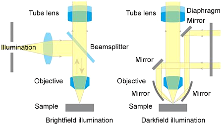
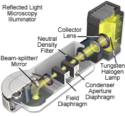
The principle of the built-in reflection type illumination at upright microscopes, is that the light coming from the source is projected both to the tube and the objective through a semipermeable layer. The diameter of the light spot is determined by apertures and diaphragms.
Automatic optical inspection
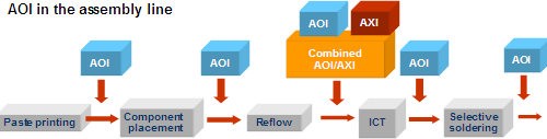
After the technological steps in assembly lines of electronics assembling companies, AOI, Automatic Optical Inspection is carried out. After each technological step, an AOI or AXI (refers to X-ray) machine can be inserted in the line. With this, up to the 100 percent of the products can be checked. The possible place of the AOI in the assembly line: after stencil printing, after component placement, after soldering, after in-circuit test or after selective soldering.
Operation: from multiple viewing angles and with different illumination, a digital image is made of the circuit. This image is then compared to a reference pattern, image, with a software. To recognise the acceptable mistakes, a teachable program is used. The circuit indicated faulty is again checked and if necessary, repaired by an operator.
Defects that can be detected by AOI: missing paste, smeared paste, bridging paste, missing components, misplaced or mispositioned components, open joints, solder bridges, tilted, deformed terminals.
Defects that can be detected by AOI: missing paste, smeared paste, bridging paste, missing components, misplaced or mispositioned components, open joints, solder bridges, tilted, deformed terminals.
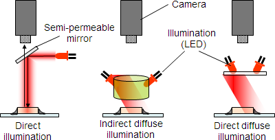
The inspected area can be illuminated in different ways. At direct illumination, the light of the light source (led) is projected through a semipermeable mirror, to the circuit. At indirect diffuse illumination, a cylinder which makes the throughpassing light diffuse, is put near the leds. The light getting to the circuit will be diffuse. At acute angle diffuse illumination, a thin slab makes the light diffuse. With this, the path direction of light is closer to the camera angle.
To improve the failure detection ratio, it is common to inspect the circuit by multiple angles. With that, we can check better the solder joints or small components that are near bigger ones. At multiple angle inspection, the picture is mirrored to the camera by a mirror placed in the adequate angle.
| Previous | Next |