
8 - Inspection and test techniques
8.2 - X-ray inspection
Principle of X-ray inspection
With X-ray microscopy, the inner structure of specimen, hidden solder joints of components, for example BGA, can be inspected in a non-destructive way. X-rays can be generated by an X-ray tube, a vacuum tube that uses a high voltage to accelerate the electrons released by a hot cathode to a high velocity. The high velocity electrons collide with a metal target, the anode, creating the X-rays. According to the material properties and structure of the specimen, the intensity of the throughpassing X-ray decreases. The detector detects the differences in these intensities. The intensity change can be calculated as:where is the attenuated intensity, is the source X-ray intensity, /is the Mass Attenuation Coefficient, is the density of the material, and is the thickness of the material.
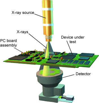
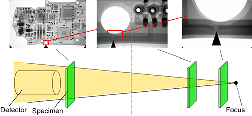
The magnification of an X-ray system is determined by the distance between the detector and the focus, divided by the distance between the specimen and the focus. Effective X-ray inspection only can be used on structures that produce sharp contrast, having different X-ray absorption. For example: metal and plastic, material and liquid, material and air. They are flux- and air voids in solder joints.
X-ray detectors
Indirect detector: from the scintillator, the light beam is radiated through optical lens, and detected with another phosphorus layer, which emits visible light, or a phototransistor (TFT)-matrix layer. Therefore, an analogue or a digital image is made. The digital image is processed by a computer; therefore it is easy to handle and change, and also to make measurements.
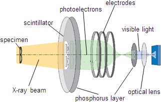
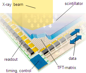
Direct detector: The X-ray passing through the specimen is projected to the scintillator. The excitable layer on it emits photoelectrons (light) according to the intensity of the X-ray directly onto the below placed TFT matrix.
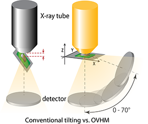
Acquiring tilted images
When making tilted images either the detector or the specimen is tilted. Tilting the detector is more advantageous, because we can reach higher magnifications. On tilted images, failures and defects are more easily recognizable. Conventional tilt techniques generate oblique views by simply tilting the sample, which involves moving the region of interest away from the X-ray tube resulting in a decrease in magnification.
The OVHM technology – Oblique Views at Highest Magnification – was specifically designed to enable oblique views of up to 70 degrees and 0 to 360 degree rotations at highest magnification. Magnification remains the same because the distance between focus and sample does not change while the detector is being tilted.
The OVHM technology – Oblique Views at Highest Magnification – was specifically designed to enable oblique views of up to 70 degrees and 0 to 360 degree rotations at highest magnification. Magnification remains the same because the distance between focus and sample does not change while the detector is being tilted.
Application field
X-ray inspection is used during failure analysis or inserted in the assembly line after soldering machines. These in-line AXI (Automated X-ray Inspection) machines automatically check the circuits, the failures are recognized with software. The samples are transported with conveyor belt. With X-ray machines, inspection of solder bumps and solder joints of BGA, CSP, surface mounted and electromechanical components, like sockets, springs, motors can be carried out. The geometry, existence of voids, solder bridging can be revealed. Conductive layers of PCBs, inner tracks, and vias can be also inspected. Inside component packages, we can check chip-and-wire bonds, but aluminium does not give a contrast to X-ray.
| Previous | Next |