
7 - Hand soldering and assembly rework
7.3 - Soldering guide for electronics components
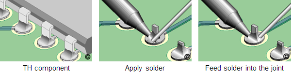
Hand soldering Through-hole components
- If needed, form the component and clean the area
- Insert the component into the plated hole. If needed, secure in place by bending leads or other mechanical means
- If needed, apply liquid flux to the plated holes and pads
- Place the soldering iron tip at the junction between the pad and component lead. Apply a small amount of solder at the junction of soldering iron tip and lead to make a solder bridge
- Immediately feed solder into the joint from the side opposite from the soldering iron tip until the proper fillet is achieved. Remove the solder then remove the iron. The iron may be swept over the end of the component lead to cover it with solder.
- On multiple lead components solder the opposite corners first to stabilize the component. Follow by soldering the remaining leads in a random pattern to reduce excessive heat buildup in one area
- Clean the flux residue, if required and inspect
Hand soldering SM components
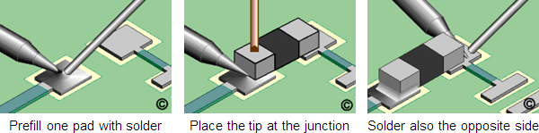
SMD passives - point to point
- Add liquid flux to one pad
- Prefill one pad with solder
- Add liquid flux to both pads
- Place the component in position and hold it steady with a wooden stick or tweezers so that the soldering iron won't push the component out of alignment
- Place the soldering iron tip at the junction between the prefilled pad and component lead. Flow the solder until the component drops down and is soldered in position. Apply additional solder as needed
- Remove the tip. Wait a moment for the solder to solidify before soldering the other side of the component
- Clean, if required and inspect
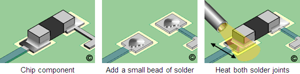
SMD passives - hot gas method
- Add a small bead of solder paste to each pad
- Place the component in position
- Adjust the pressure and temperature output of the hot air tool
- Direct the hot air over the component with the hot air tool tip approximately 2.50 cm (1.00") from the solder joint. This initial heating will pre-dry the solder paste
- When the solder paste has dried, move the hot air tool tip to approximately 0.50 cm (0.20") above the component. Move the tool back and forth to heat both solder joints until complete solder melt is observed
- Wait a moment for the solder to solidify
- Clean, if required and inspect
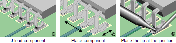
J lead components – point to point
- Add liquid flux to the corner pads
- Place the component in position and hold it steady. The leads must be aligned with the pads. On large components this is best done by aligning the leads on opposite corners
- Place the soldering iron tip at the junction between the pad and component lead at one of the corners. Apply additional solder as needed
- Remove the tip. Wait a moment for the solder to solidify before soldering the opposite corner
- After the opposite corner is soldered, solder the remaining leads
- Clean, if required and inspect
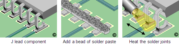
J lead components – hot gas method
- Add a small bead of solder paste along the row of pads
- Place the component in position
- Adjust the pressure and temperature output of the hot air tool
- Direct the hot air over the component with the hot air tool tip approximately 2.50 cm (1.00") from the solder joint. This initial heating will pre-dry the solder paste
- When the solder paste has dried, move the hot air tool tip to approximately 0.50 cm (0.20") above the component. Move the tool back and forth to heat all the solder joints until complete solder melt is observed
- Remove the tool. Wait a moment for the solder to solidify
- Clean, if required and inspect
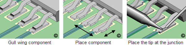
Gull wing components – point to point
- Add liquid flux to the corner pads
- Place the component in position and hold it steady. The leads must be aligned with the pads. On large components this is best done by aligning the leads on opposite corners
- Place the soldering iron tip at the junction between the pad and component lead at one of the corners. The soldering iron tip may rest at the junction of the component lead and pad or on top of the lead. Apply additional wire solder as needed
- Remove the tip. Wait a moment for the solder to solidify before soldering the opposite corner
- After the opposite corner is soldered, solder the remaining leads
- Clean, if required and inspect
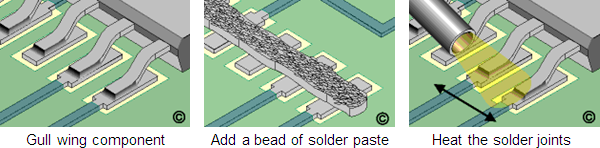
Gull wing components – hot gas method
- Add a small bead of solder paste along the row of pads
- Place the component in position
- Adjust the pressure and temperature output of the hot air tool
- Direct the hot air over the component with the hot air tool tip approximately 2.50 cm (1.00") from the solder joint. This initial heating will pre-dry the solder paste
- When the solder paste has dried, move the hot air tool tip to approximately 0.50 cm (0.20") above the component. Move the tool back and forth to heat all the solder joints until complete solder melt is observed
- Remove the tool. Wait a moment for the solder to solidify
- Clean, if required and inspect
| Previous | Next |