
4 - Component placement methods
4.2 Mechanism of actuation
Walking beam machines
Walking-beam machines. The walking-beam-style machine is designed for extremely high-volume production environments. PCBs usually are mounted on a pallet just prior to assembly and then the pallet is indexed step-by-step through a number of placement stations. This style machine is extremely popular with a very small, but highly respected market segment. Although the design is very efficient, it is not very friendly when changing from one product to another. To change to a different product, the pallets must be adjusted, the feeders repositioned and the heads retooled, limiting popularity to products requiring nonstop production of a limited number of products.
Gantry-style machines
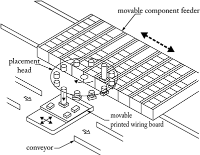
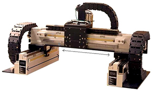
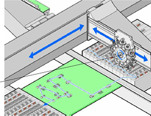
Gantry-style machines use a placement head mounted on a beam, allowing the placement head access to all the feeder positions as well as the circuit board. The component feeders and the PCB all remain stationary in this design, and the pick-up head mounted on the gantry goes to the feeders, gathers the components, image processes the parts and then delivers them to the correct placement point on the circuit board. To increase speed, gantry-style machines often have many nozzles on a single head and may use more than one gantry per machine, in sort of a "tag team" approach. As one head is collecting parts, the other is placing parts, and vice versa.
Placement heads - pick and place
Pick and place machines pick and place components one by one. The efficiency of these machines is up to 20 000 components per hour. The accuracy of these machines is relatively high (10–20 µm), therefore fine-pitch IC packages are always placed with pick and place heads.
Collect and place machines
Collect and place machines collect several components from the feeder and then placing them onto the printed circuit board. The efficiency of these machines is up to 80 000 components per hour.
The accuracy of these machines is relatively low (30–40 µm), they are appropriate for placing small SMD components, which do not require high accuracy.
Component placement failures
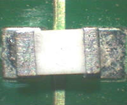
Typical component placement failures occur because of the inaccuracy in the size of the components; inaccuracy in the pattern of the PCB; wear of the nozzles; and because of the positional / rotational offset of the machine itself. The failures are:
- Component falls down from the nozzle
- Misplacement, and rotational offset of the placed component
- Wrong polarity
 |
 |
Determining machine capability
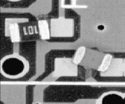
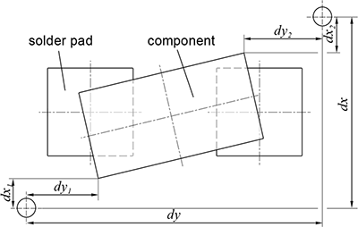
To characterise the positional offset of the placement machines, and to estimate the expected failure rate, the machine capability can be determined. To determine the capability, the average and the standard deviation of the positional offset should be measured. Such a testpattern can be used for the measurements, which contains reference marks (fiducials) nearby the SMD passives, and the position of the components' corner can be measured to the fiducial marks.
By placing many SMD passives into a two-sided adhesive (e.g. 1000 pcs.), and by measuring their positional offset, the average and the standard positional offset can be calculated.
The machine capability can be calculated by defining upper- and lower specification limits. The specification limits for SMD passives are usually equal to the quarter length of the component's shorter side. Stricter specification limits can although be used. The capability index indicates how accurate our process or machines is compared to a process.
The capability index in the case of average positional offset is zero:
The capability index in the case of average positional offset is not zero: where is the process or machine capability, is the corrected process or machine capability, and are the upper and lower specification limits, is the deviation of positional offset, is the average of the positional offset, and is a coefficient, which is generally 3 for process capability and 4 for machine capability. However, always value of 3 is used in the industry for calculating either process or machine capability. It should be noted, that . After calculating the capability index, the expected failure rate can be estimated. The failure rate in [ppm] means that how many components will be misplaced (positional offset is greater than the specification limits), when placing one million components.
Estimated failure rate based on capability index
| Process | Failure rate [ppm] |
|
|---|---|---|
| < 1 | Process or machine is incapable | |
| 1 | ≤ 2 700 | |
| 1.33 | ≤ 63 | |
| 1.66 | ≤ 0.57 | |
| 2 | ≤ 0.002 | |
| > 2 | Process or machine is outstanding | |
| Previous | Next |