
7 - Electronic devices and appliances
7.1. Thermal constructions of electronic appliances
Necessity of thermal construction
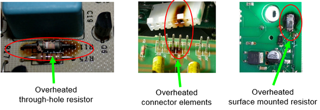
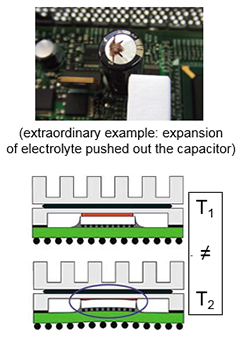
Heat arises in the electronic components during operation. Appliances are exposed to heat effects coming from the ambiance. The heat and the fluctuation of the heat can be harmful (disturbing function)
Effects of the heat and the fluctuation of heat
High temperature: chemical decomposition of materials, diffusion becomes faster, softening, degradation of polymers, reversible or irreversible change of electric parameters, intermetallic layer formation, corrosion. Fluctuation of the temperature: mechanical stress, can arise due to the different, thermal expansions.
Types of heat transport mechanisms
Heat condiction: Conduction is the transfer of thermal energy in solid materials realized by energy transfer among fixed particles and by diffusion of free moving particles due to a temperature gradient.
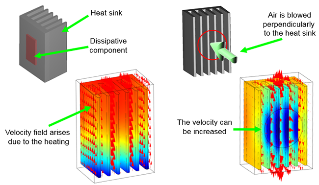
Heat convection: The heat transfer of thermal energy in gases and liquids is realized by ordered movement (flow) of particles. Molecular level heat conduction and radiation also can play a role. Evolution of velocity field can be: natural (density of materials is function of the temperature, so flow is arising from heating) and forced (artificial circulation of gas of liquid).
Comparison of natural and forced convection:
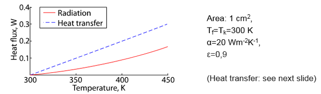
Heat radiation: Thermal radiation is electromagnetic radiation emitted from a material. Comparison of the heat transfer and radiation:
Heat transfer: Heat transfer between fluids (gases) and solid surfaces depends on the heat transfer coefficient. Here conduction, convection and radiation plays role as well. The efficiency of heatransfer coefficient depends on: quality of the surface; flow properties of fluid/gas (turbulent, laminar); physical properties of the fluid/gas (temperature, pressure, velocity, laminar/turbulent flow).
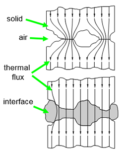
Heat transfer between solids
All of heat transfer phenomena take place in the interface: conduction (often the conduction of the oxides of the solid material); heat transmission (air); radiation.
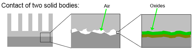
This interface can mean high thermal resistivity, which can be reduced by: polishing of the surfaces; pressing of the surfaces; soldering the surfaces to each other; applying thermal interface.
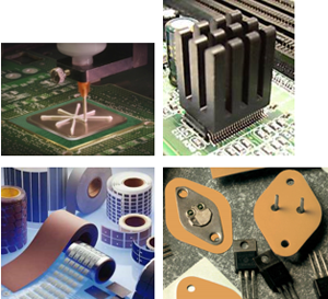
Thermal interface materials
Thermal interface materials: they fill the gaps due to their elasticity and viscosity and they have quite good thermal conductivity (compared to air) their reactive components improve the quality of surfaces.
Aspects of application: thermal conductivity; electrical conductivity; elasticity and spreading; long-term stability and reliability and easy application.
Realization:
- paste
- adhesive
- pre-formed sheet
- phase-change materials
Paste: suspension of metal flakes; the surfaces have to be pressed together also during operation; the application is complicated.
Adhesive: ceramic powder in UV- or heat curable suspension; after curing, surfaces do not need to be pressed together; conductive types also exist; moderate thermal conductivity.
Pre-formed sheet: mostly they are polymers with high thermal conductivity; the surfaces have to be pressed together; moderate elasticity (they do not fill the gaps completely); good insulators and have high breakdown voltage.
Phase-change materials: suspension of metal flakes or ceramic powder; the surfaces have to be pressed together; effective gap filling due to low melting point; the application can be automated.
Thermal constructions
Thermal construction of the appliances assures the removement of heat arising in active devices. The two level of thermal design:
Device level: according to determined quantities (temperatures, powers), quite simple calculations not necessary for every components
Appliance level: there are no determined quantities; series of comlex calculations; n the case of several subsystems, we must do thermal construction for all subsystems.
Device thermal desgin
Thermal model of a device and its cooling using thermal-electrical analogy:
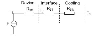
P: dissipated power, W,
Tj: temperature of the device, °C (catalogue),
Ta: temperature of the ambient, °C,
Tc: temperature of the case, °C,
Rthc: thermal resistance of case, K/W (catalogue),
Rthi: thermal resistance of interface, K/W (catalogue),
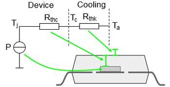
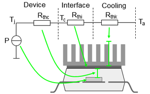
Rthk: thermal resistance of cooling, K/W
Thermal resistance from the surface of the chip to the environment:
whereis the heat transfer coefficient, andis the size of surface of the device.
Thermal resistance from the surface of the chip to the environment:
where is the average length of heat flux inside the sink is the thermal conductivity of the sink, is the avarage cross-section, is the heat transfer coefficient of the sink, and is the area of surface of the sink.
.
Appliance level thermal design
Appliance level design: non-standardized elements; definite solution does not exist; aspects of construcion has to be taken into consideration as well.
Difficulties of the objective in the calculations: time-dependent phenomena have to taken into consideration; often non-linearities have to be taken into consideration; coupled physical effects have to taken into consideration;parameters of the materials can be varied (reversible and/or irreversible); the geometry under investigation is very complex; the boundary conditions (parameteres of the ambient) can be uncertain.
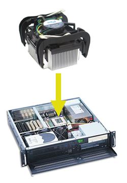
Cooling solutions
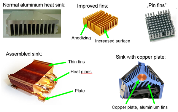
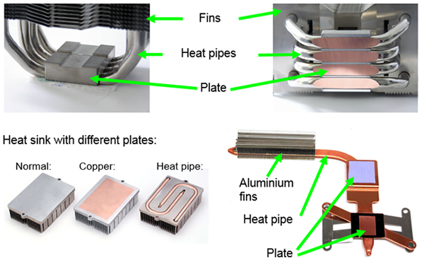
Heat sinks and plates
Applied materials:
Aluminium: low-cost; processable easily; good heat transfer to ambient.
Copper: expensive; difficult to process; good thermal conductivity; worse heat dissipation (silver, metal foam, graphite, diamond…)
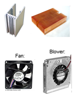
Enhancing dissipation by forced convection. Types of ventilators: fan and blower. Most important parameters are the revolutions per minute;the dimensions;the angular offset of blades; the shaping of blades and the noise.
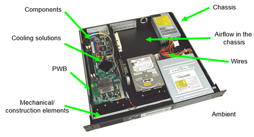
Cooling solutions on PWBs
The printed circuit board plays a role in the thermal management. Thermal behavior of the PWB can be improved width: continuous copper layers: copper inlay, thermal vias, ceramic substrate.
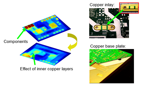
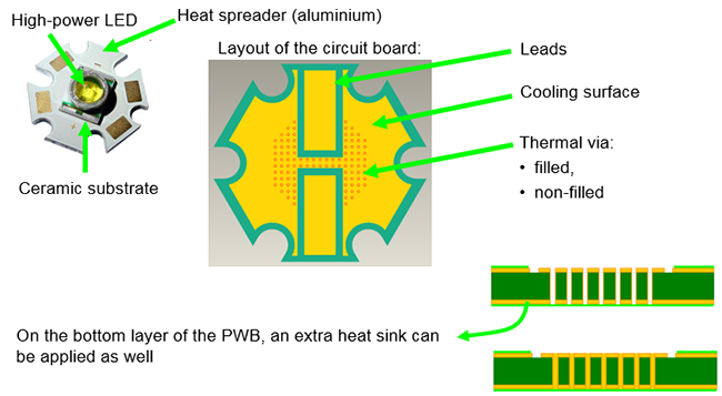
Thermal Via:
Liquide cooling:
Motivation: The specific heat capacity of liquids is high (air: 0,001 J.cm-3.K-1, water: 4 J.cm-3.K-1), thermal conductivity of liquids is higher than that of gases (air: 0,026 W.m-1.K-1, water: 0,61 W.m-1.K-1), for this reason the heat transfer of the boundary is better (air: 20…200 W.m-2.K-1, water: 500…10000 W.m-1.K-1).
Properties: high cooling power and lower component temperature can be arisen (compared to air cooling); low noise; long lifetime, closed system (contamination can not come from ambience), high reliability; the realization is complicated and size and mass is higher, shock-resistivity is lower.
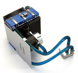
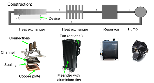
Realization types: indirect and direct.
Indirect liquide cooling: the liquid does not contact the electric components.
Direct liquide cooling:
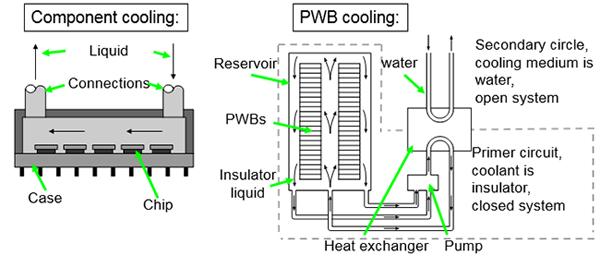
Direct liquid cooling: the liquid contacts the electric components directly (heat exchangers are avoided). Properties: the thermal resistance is decreased between the liquid and component, the liquid has to be insulator, realization is difficult.
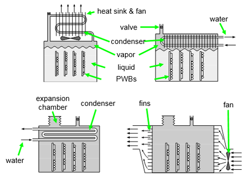
Phase change cooling:
Motivation: the evaporation of a liquid absorbs heat from the electric component, more heat than with circulation the same liquid (see latent heat, e.g. 1 kg of water has 2,26 MJ latent heat). Realizations:
Direct: the system with gas tank: with external condenser, or internal condenser. System without gas tank: internal cooling or external cooling.
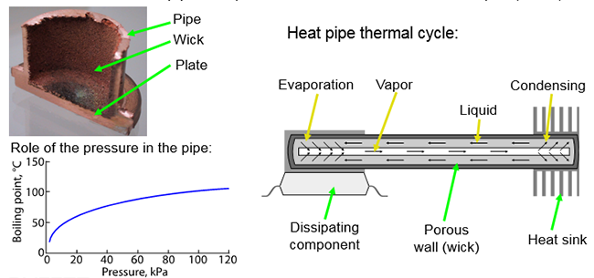
Indirect: heat pipe.
Heat pipe: a phase-change liquid cooling system in a compact form to decrease the thermal resistance. Thermal conductivity of a heat pipe is 100…1000 times higher than that of copper. Construction: vacuum pipe with porous wall, and small volume of liquid (water).
Peltier cooling:
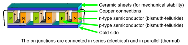
Peltier-cell: thermoelectric heat pump (dissipation on the hot side is necessary!) Realization: Applying of Peltier cell is necessary in space applications and in the case of reducing thermal noise (e.g. CCD chip), using multiple units, -150°C can be reached!
The energy level in p- and n-type semiconductor is different. When the electrons step over, the difference of the energy must be absorbed from the environment, in which event the junction is cooled/heated up.
| Previous | Next |