
4 - Component placement methods
4.1 - Type of placement machines
Classification of placement machines
Placement machines supposed to place the electronic components into the deposited solder paste. They can be classified by:
- The degree of automatization: manual, semi-automatic, automatic
- The mechanism of actuation: Gantry style, walking beam style
- The type of the placement head: pick and place, collect and place
Manual placement machines
Manual Placement can be accomplished in many ways, the simplest of which would be using a pair of tweezers and a table. In this method, a person would simply take the components and put them on the appropriate spot by hand. Manual placement still is used in many areas today – mainly in rework – but sometimes with the addition of a late part or with very small prototype builds. There are many reasons why this is not the best component placement method. Four of them are key:
Accuracy: The likelihood of errors increases significantly when someone is hand placing a part. When getting into fine-pitch components, it is very difficult to achieve the accuracy necessary for functionality when placing a part by hand. Additionally, the likelihood of placing the wrong components or placing the part in the wrong place is high.
Speed: Placing parts by hand is simply too time consuming.
Orientation: Even if a part is hand-placed in the right spot, it is easy to place it in the wrong orientation. Many components are polarized and placing them in the wrong direction will cause the board to fail.
Technology: As parts get smaller and smaller, they become more difficult to handle. Typically, they have few identification marks, often requiring underside inspection to be placed manually. The newest generation of mini components is the 0201. They are barely bigger than grains of sand and have no markings to identify their type or value.
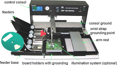
Semi-automatic placement machines
This level of placement, semi-automated machines, comes in a wide range of sizes and capacities. They start with what generally is termed an "entry-level" machine – a relatively inexpensive, small but versatile piece of equipment that can pick-and-place a large variety of parts with a fair amount of speed and accuracy. Entry-level machines typically place parts in the range of 3 000 to 5 000 parts per hour.
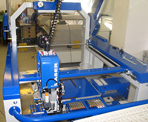
Automatic placement machines
Slightly more advanced and more expensive than entry-level machines, mid-range machines essentially have the same capabilities as their entry-level counterparts. However, they often will hold more component feeders, and they place components faster. A mid-range machine usually will place between 8 000 to 14 000 components per hour. High-end machines take placement speed considerably further – to the 20 000 to 30 000 per hour range.
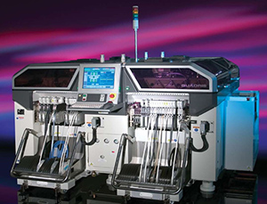
At this point, placement machines typically are split into two categories: high speed and flexible placement. The reason for this is the inherent conflict between speed and accuracy.
Usually, about 80 per cent of the components on a board are resistors and capacitors, which need to be placed quickly. With these components, accuracy is not as critical as with other components on the board. Larger, more complex components (e.g., flat package integrated circuits (QFP), ball grid arrays (BGA), direct attach chips) demand higher placement accuracy, so speed may be sacrificed in these instances. Finally, the ultra-high-speed chip placers are machines that typically place 40 000 to 100 000 components per hour. They are amazingly fast, quite easy to changeover and use many parts reels. At the high- and ultra-high-end equipment are the chip-shooter-style machines, which are available in three distinct types. The most popular is the turret-style machine, the second is the gantry-style machine and the third is the walking-beam-style machine. Each style has its own unique characteristics.
Placement of fine-pitch components in rework
Usually in the case of repair or rework of BGA (ball grid array), CSP (chip scale package) or FC (flip chip) components with bump terminations on the bottom side of their package, or rework of very fine pitch surface mount components, like QFPs (quad flat packs), those components are placed by hand to a board using highly sophisticated place machines with precise optical alignment systems. To reach high placement precision, the bottom of the package (leads) and the surface of the PCB is overlaid onto each either by an optical system (prism) or by a camera system.
| Previous | Next |